Grounding system design in electrical substations protects engineers, technicians, and electrical equipment from dangerous fault currents. A properly engineered substation grounding system ensures that fault current flows safely into the earth and prevents hazardous step voltage and touch voltage conditions.
- substation grounding network in electrical substations
substation grounding network in Electrical Substations
Grounding system design in electrical substations forms the foundation of electrical safety in power systems. Substations contain transformers, circuit breakers, steel structures, and control equipment that must connect to a grounding grid. The substation grounding network ensures that fault currents safely dissipate into the earth without creating dangerous voltage differences across the substation yard.
Soil Resistivity Measurement for Grounding System Design
Soil resistivity measurement is the first technical step in substation grounding system. Engineers must understand how easily electrical current flows through the earth before designing a grounding grid. The most common method used by engineers is the Wenner four electrode test. Accurate soil resistivity values help engineers determine grid size, conductor spacing, and the number of grounding rods required for safe fault current dissipation.
Step Voltage and Touch Voltage Safety in substation grounding system
Step voltage and touch voltage represent the main safety risks addressed by grounding system design. Step voltage occurs when a person walks across the ground during a fault condition and experiences a voltage difference between two points on the surface. Touch voltage occurs when a person touches grounded equipment while standing on the ground. Proper grounding grid design distributes fault current across the soil and reduces dangerous voltage differences within the substation area.
IEEE 80 Standard for substation grounding system
IEEE 80 is one of the most widely used standards for grounding system design in electrical substations. The standard provides engineering methods for calculating grid resistance, determining safe step voltage and touch voltage limits, and designing grounding grid layouts. Engineers rely on IEEE 80 guidelines to ensure that grounding systems protect both personnel and equipment during electrical fault conditions
IEEE 80 grounding design standard provides detailed engineering guidelines for safe substation grounding network in electrical substations.
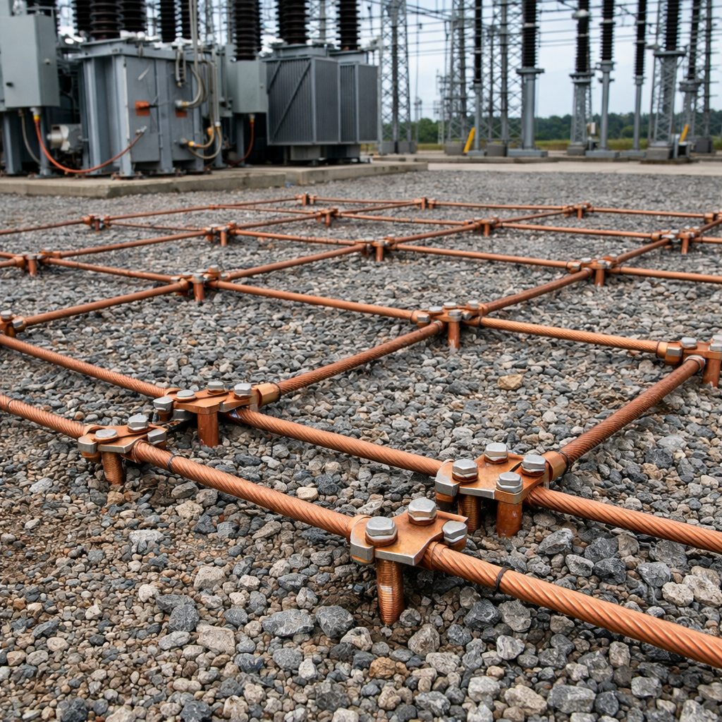
Grounding Grid Layout in Substation Design
Grounding grid layout plays a critical role in substation safety. Engineers normally install copper conductors in a mesh pattern under the substation yard. This mesh distributes electrical fault current across a large surface area and reduces dangerous voltage differences on the ground surface.
Grid spacing depends on soil resistivity and fault current magnitude. Smaller spacing improves safety but increases installation cost. Engineers therefore balance safety requirements and economic considerations during grounding grid design.
Importance of Proper Grounding Maintenance
Even a well designed grounding system requires periodic inspection and maintenance. Corrosion of buried conductors or damaged connections may increase grounding resistance over time.
Utilities perform grounding resistance tests and visual inspections during maintenance schedules. Maintaining a reliable grounding network ensures long term safety for personnel and electrical equipment inside substations.
Outstanding post however I was wanting to know if you could
write a litte more on this subject? I’d be very thankful if you could elaborate
a little bit more. Kudos!